| NOTE: If you are replacing an existing adapter with a new adapter, you must re-install the driver. |
|
|
CAUTION: Turn off and unplug the server before removing the server's cover. Failure to do so could endanger you and may damage the adapter or server. |
|
|
NOTE: The Intel® 10 Gigabit AT Server Adapter will only fit into x8 or larger PCI Express slots. Some systems have physical x8 PCI Express slots actually support lower speeds. Please check your system manual to identify the slot. |
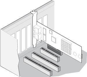
|
|
CAUTION: Some PCI-Express adapters may have a short connector, making them more fragile than PCI adapters. Excessive force could break the connector. Use caution when pressing the board in the slot. |
If your computer supports PCI Hot Plug, see your computer documentation for special installation instructions.
Shut down the operating system.
Turn off and unplug your computer. Then remove the cover.
|
|
CAUTION: Turn off and unplug the power before removing the computer's cover. Failure to do so could endanger you and may damage the adapter or computer. |
Remove the cover bracket from a PCI (v2.3 compliant) bus master slot, or a PCI-X (v1.0a compliant) slot. (This adapter uses 3.3v signaling.) If you have configuration problems, see your computer's documentation to determine if the PCI slots are bus master-enabled.
PCI and PCI-X bus theoretical speed designations are shown below:
| 33 MHz | 66 MHz | 100 MHz | 133 MHz | ||
| 64-bit | "2x" | "4x" | "6x" | "8x" |
| NOTE: Intel highly recommends installing the Intel® PRO/10GbE CX4 Server Adapter in a 133MHz PCI-X slot. Slower slots will significantly degrade adapter performance. For example, a 32-bit 33MHz PCI slot cannot achieve more than 5% of the theoretical bandwidth of a 10-gigabit full duplex connection. |
|
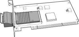 |
|
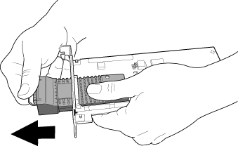 |
|
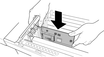 |
|
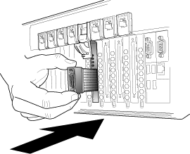 |
Repeat steps 4 through 8 for each additional adapter to be installed.
Replace the computer cover and plug in the power cord.
Turn the power on and start your operating system.
If you get a PCI or PCI-X configuration error, see Bus Configuration Troubleshooting.
Last modified on 6/13/08 10:17a Revision 4